• After 15+ years, we've made a big change: Android Forums is now Early Bird Club. Learn more here.

Root Wireless Charging

A while back someone asked if we could wirelessly charge with the metal contacts that are on the side of our phone. It was confirmed that they did not touch the motherboard so it would not work. That post got me digging on how wireless charging worked and I want it now. Unfortunately our phone is very thin and the back is metal which charging can't go through so it may just need to be between the extra case and the phone. I bought a wireless charging pad form hong kong for $20 and a droid charge back cover with wireless charging for $10. Some people go with the palm treo/pixi but I like the QI standard as it allows about 4 cm range for a case and it seems like it will be the winning standard with oem products.

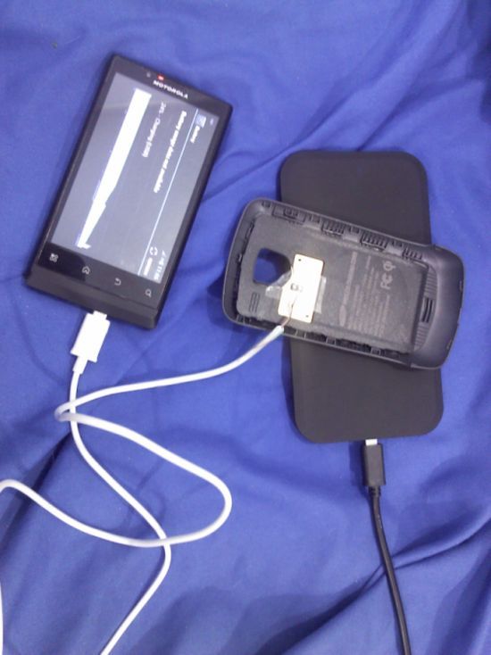
Below is a pic of the droid charge case on a wireless charging pad with a micro USB cable stripped attached to the droid charge case and plugged into the phone USB port. It works but I will need to open up the phone and connect to the motherboard because loosing a USB port is unacceptable.

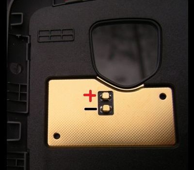
Droid Charge case polarity

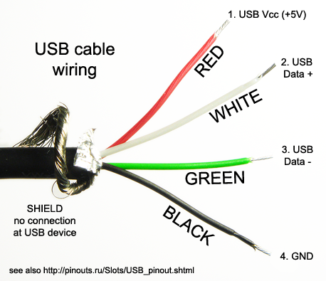
usb cable pin-out

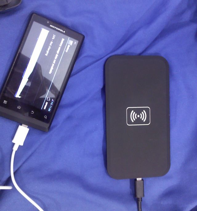
Not Charging

Charging at an angle.

FYI I know next to nothing about electricity and that sort of thing. I know that it charges at about 5V and 500mA. The positive wire needs to connect to some positive (using a multimeter) spot on the motherboard and the negative can so to any ground like the sd card slot or a screw. I would like to get it in the phone rather than outside and the components are about 1 to 2 mm thick when you take them out of the droid charge case.

I could not find anyone that had done this before with our phone so if anyone has any insight on where if could be placed or what I could connect the positive terminal to or any ideas please let me know!
 
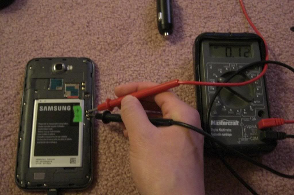
I took the cover off and probed the phone with a multimeter and at best I got 0.02 but as a charging spot it needs be be around 0.12 as seen in the pick of the Galaxy Note 2 below.


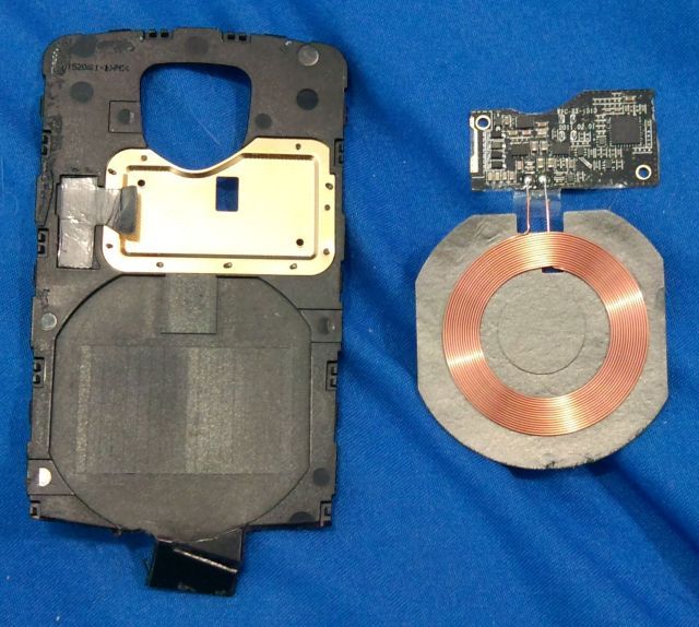
I took the motherboard out and now nothing registered a charge. Possibly because the phone was off and none of the components were now connected to the motherboard. This was totally possible and the final droid charge components were about 1 mm thick and they would have probably fit. See the image below of the components on the right.


I am sorry to say but I could not locate a suitable terminal to connect the positive wire to. If anyone knows where one is or would be willing to probe their phone to find one I would be willing to try this again.
 
This would have been so useful to me about a year or more ago.

I would highly recommend using the USB port as this is regulated. When it detects a low current charger it is where the 500mA are limited (sort of). If it detects a high rate charger (A\C) it will charge at 1000mA. If you did something like going straight to the battery you risk the potential of overcharging the battery, or worse.

I would look at how the charging device connects to the USB port and mimic that on the motherboard at the USB connections. The wires are very small, too small for my soldering skills, so be careful.

I thought about soldering straight to the back of the USB port but the port is covered and you can't get to the pins. It seems like other people that have done it, found some metal contact somewhere on the board that the power went through and they soldered to that as it is a bigger area.

I tried to find that metal contact but I think it is on the side that the usb is connected to which you cant get to easily without disconnecting some of the cables which I think stops the power from going through the board.

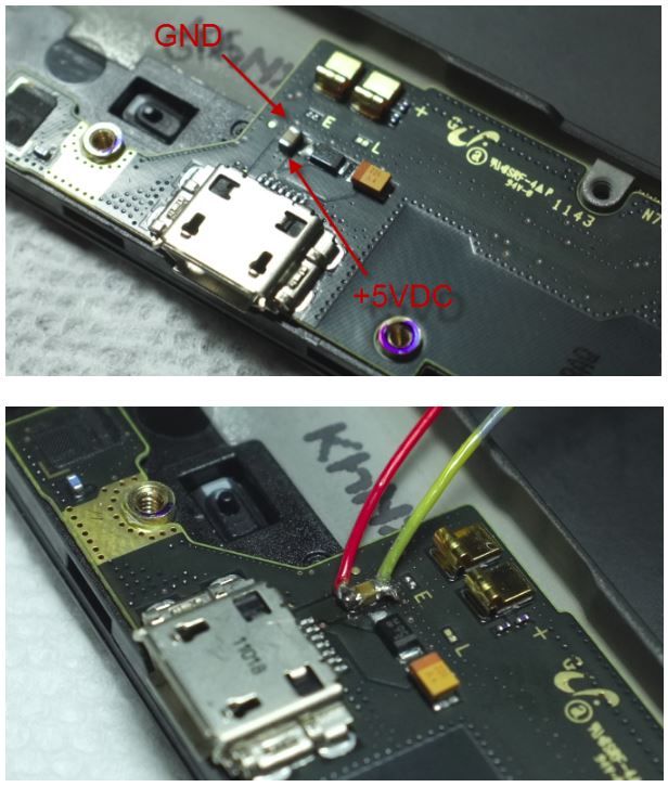
Below is a pic of the note 2 where someone soldered to the positive and ground terminal as it was one small chip (below). I think I saw a chip that looked identical to that on our phone. I tried digging but couldn't find the post that showed our motherboard. Can you please link the post if you remember where it was.

 
Does anyone remember where the post is where someone took pictures of the internals of the phone with the motherboard? I've gone back like 3 pages and can't locate it.
 
Does anyone remember where the post is where someone took pictures of the internals of the phone with the motherboard? I've gone back like 3 pages and can't locate it.

http://androidforums.com/motorola-triumph/722925-pics-triumph-anatomy-gut-shots.html
Here's my thread, if that's what you mean. (still page 1 of Motorola Triumph forum)
fwiw, I went through my original full-res shots yesterday, and can't find anything of benefit. If you think any of them may help you, I can email them I guess... or post a different crop?
 
Thank you so much thangfish! I see what I'm looking for and I'm getting ready to go inside again this weekend if I can make time.
 
I am still fascinated by wireless charging and by taking my phone apart again, I am accepting the risk that my phone may not turn on again or anything could go wrong but I am still pushing forward. Plus our phone can't possibly be that expensive now to replace and I have a spare if it does go badly.

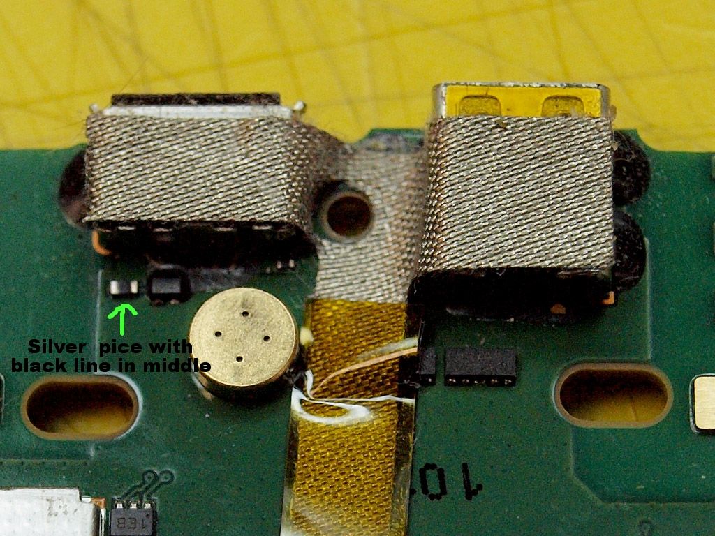
The first pic I think is a galaxy s2 or note 2. In front of the USB port, there is a black square next to a silver rectangle with a black bar in the middle that they soldered the power cable to. Our phone appears to have the same silver with black bar across it. I'm going to test it this weekend but I would love to hear the communities thoughts.

Samsung Phone:


Motorola Triumph

(I spelled piece wrong in the pic. You get the picture)
 
Not much help.
P5214615usbdetail1024x768.jpg


I was using a macro lens, but I didn't bother getting out the tripod so the depth of field just isn't there. I can zoom in further, but it's pointless it's so blurry.

my guess would be that it's most likely a diode, but it's impossible to tell if there's any numbers on it.
 
I am still fascinated by wireless charging and by taking my phone apart again, I am accepting the risk that my phone may not turn on again or anything could go wrong but I am still pushing forward. Plus our phone can't possibly be that expensive now to replace and I have a spare if it does go badly.

The first pic I think is a galaxy s2 or note 2. In front of the USB port, there is a black square next to a silver rectangle with a black bar in the middle that they soldered the power cable to. Our phone appears to have the same silver with black bar across it. I'm going to test it this weekend but I would love to hear the communities thoughts.

Samsung Phone:

Motorola Triumph

(I spelled piece wrong in the pic. You get the picture)

You could try and check if the suspected contact points are directly connected to the USB port with an ohm meter. If you have next to no resistance then you probably have the right wiring. If you have some resistance then you probably have something that may not work. I would hate to see you let the smoke out of the MT.
 
The little black component is likely an inductor. If that is on the 5V input pin (probably is) be sure to solder on the side that goes to the external USB port pin and not the side running into the phones charge circuit. The inductor 'cleans' the incoming power.
 
So by my understanding, what you're trying to do is wire the charging pad's receiver to the mobo of the Triumph, then glue it on or something?


Because if so you're a god damn genius and my Triumph would surely be an attention getter now, especially since it's been retired for a few months now.
 
So by my understanding, what you're trying to do is wire the charging pad's receiver to the mobo of the Triumph, then glue it on or something?


Because if so you're a god damn genius and my Triumph would surely be an attention getter now, especially since it's been retired for a few months now.

That is exactly what I'm planning on doing. I can't sacrifice the usb port so I need to find a positive lead to solder to on the motherboard. The negative wire can go to a screw or some metal part of the case so that is no big deal. I want to upgrade soon so i'm not too worried about destroying the Triumph but I would like this to work as it would be awesome! I'm a little confused with knowing which way the current is flowing as mozzwald mentioned but it looks to be the same sort of arrangement as the other Samsung phone that was soldered to so I'm thinking it will test positive with my multimeter.
 
That is exactly what I'm planning on doing. I can't sacrifice the usb port so I need to find a positive lead to solder to on the motherboard. The negative wire can go to a screw or some metal part of the case so that is no big deal. I want to upgrade soon so i'm not too worried about destroying the Triumph but I would like this to work as it would be awesome! I'm a little confused with knowing which way the current is flowing as mozzwald mentioned but it looks to be the same sort of arrangement as the other Samsung phone that was soldered to so I'm thinking it will test positive with my multimeter.

Plug in a usb cable and put you DMM in DC voltage mode. Put your black lead on a known ground and red lead on one side of the inductor. You should get a reading around 5V.

Finding the side of the inductor that runs to the port is a bit harder. Easiest way is to look for a trace that comes from under one side of it and either runs to the port or to some circuitry/chips/components. The hard way is to remove inductor and use your DMM in continuity mode to test from each pad to a stripped usb cables positive wire.
 
I pulled the phone apart this weekend and wireless charging isn't going to happen. :(
I could not find a positive spot on the board except the small pin from the usb port. Even if I was able to solder a wire to the pin Our back is metal and it would have to be attached to the back which slides with the case over it. It just isn't practical so I am throwing in the towel.The phones where people have done this the entire back cover snaps on and can bend a little to accommodate the charging coils but our phone would just be unpractical.

If anyone wants some pics let me know as I took some while I was inside.
 
Back
Top Bottom